Waste Management Internship
Schematics
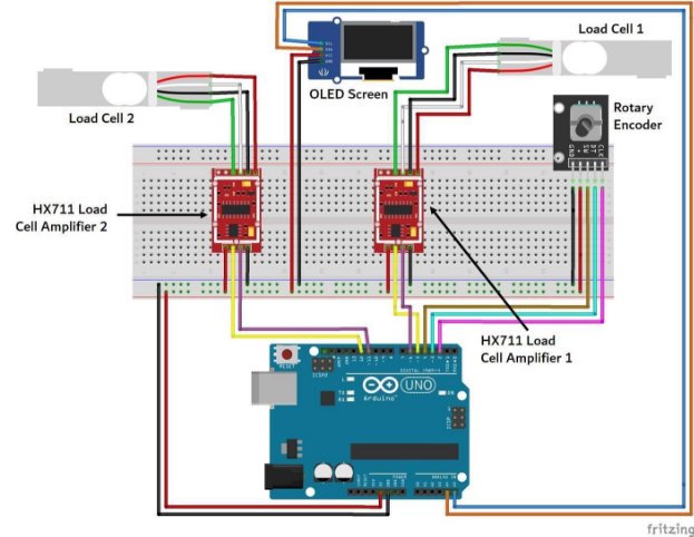
This image is the schematic of the Arduino and the connections to the rest of the electrical components.

The list of the components: Google Sheets
An explanation of how the entire system works: Google Drive
The design of the device is described below. The code necessary to run the device is also written below.
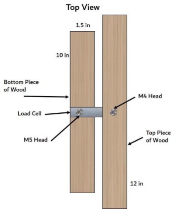
The Design: Top View
The picture below is the top view of the device that I built, which utilizes 2 screws with different head, the M4 and the M5, to screw onto pieces of the wood (the load cell itself has 2 screw holes on each side; it is important that the M4 head is on the same side where the wood is screwed on to the top (there is also an arrow on that side, showing the direction the load cell needs to be pointing, and where the mass should be applied)

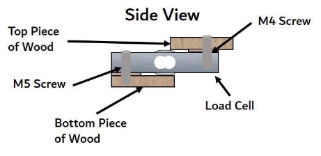
The Design: Side View
The picture below is the side view of the load cell, where one important thing to note is the spacers that prevent the wood to directly touch the epoxy on the load cell as that cannot have any direct force applied since the Wheatstone bridge (how a load cell works, by having the resistance change when a mass is applied) is directly beneath there.

The Code
To view the code, please click here.